(Hong Kong)

Product Summary
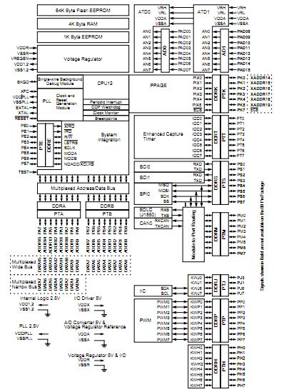
The mc9s12d64cfue is a 6-bit device composed of standard on-chip peripherals including a 16-bit central processing unit, 64K bytes of Flash EEPROM, 4K bytes of RAM, 1K bytes of EEPROM, two asynchronous serial communications interfaces (SCI), one serial peripheral interfaces (SPI), an 8-channel IC/OC enhanced capture timer, two 8-channel, 10-bit analog-to-digital converters (ADC), an 8-channel pulse-widthmodulator (PWM), a digital Byte Data Link Controller (BDLC), 29 discrete digital I/O channels, 20 discrete digital I/O lines with interrupt and wakeup capability, a CAN 2.0 A, B software compatible modules, and an Inter-IC Bus. The mc9s12d64cfue has full 16-bit data paths throughout. However, the external bus of the mc9s12d64cfue can operate in an 8-bit narrow mode so single 8-bit wide memory can be interfaced for lower cost systems. The inclusion of a PLL circuit allows power consumption and performance to be adjusted to suit operational requirements.
Parametrics
mc9s12d64cfue absolute maximum ratings: (1)I/O, Regulator and Analog Supply Voltage, VDD5: -0.3 to 6.0 V; (2)Digital Logic Supply Voltage, VDD: -0.3 to 3.0 V; (3)PLL Supply Voltage, VDDPLL: -0.3 to 3.0 V; (4)Voltage difference VDDX to VDDR and VDDA, VDDX: -0.3 to 0.3 V; (5)Voltage difference VSSX to VSSR and VSSA, VSSX: -0.3 to 0.3 V; (6)Digital I/O Input Voltage, VIN: -0.3 to 6.0 V; (7)Analog Reference VRH, VRL: -0.3 to 6.0 V; (8)XFC, EXTAL, XTAL inputs, VILV: -0.3 to 3.0 V; (9)TEST input, VTEST: -0.3 to 10.0 V; (10)Instantaneous Maximum Current Single pin limit for all digital I/O pins, ID: -25 to +25 mA; (11)Instantaneous Maximum Current Single pin limit for XFC, EXTAL, XTAL, IDL: -25 to +25 mA; (12)Instantaneous Maximum Current Single pin limit for TEST, IDT: -0.25 to 0 mA; (13)Storage Temperature Range, Tstg: -65 to 155 ℃.
Features
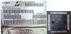
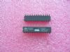
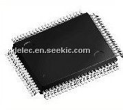
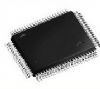
mc9s12d64cfue features: (1)HCS12 Core 16-bit HCS12 CPU; (2)8-bit and 4-bit ports with interrupt functionality; (3)Memory 64K Flash EEPROM; (4)Two 8-channel Analog-to-Digital Converters; (5)1M bit per second, CAN 2.0 A, B software compatible module; (6)Enhanced Capture Timer; (7)8 PWM channels; (8)Serial interfaces; (9)Byte Data Link Controller (BDLC); (10)Inter-IC Bus (IIC); (11)112-Pin LQFP or 80 QFP package.
Diagrams
| Image | Part No | Mfg | Description |  |
Pricing (USD) |
Quantity | ||||||||||||
|---|---|---|---|---|---|---|---|---|---|---|---|---|---|---|---|---|---|---|
 |
 MC9S12D64CFUE |
Freescale Semiconductor |
16-bit Microcontrollers (MCU) 64K FLASH HCS12 MCU |
Data Sheet |
|
|
||||||||||||
|
MC9S12D64CFUER |
Freescale Semiconductor |
16-bit Microcontrollers (MCU) 64K FLASH 9S12 MCU TORPE |
Data Sheet |
|
|
||||||||||||